Relay Outputs
By now we should have a good understanding of how the inputs are used. Next up is the output circuits.
One of the most common types of outputs available is the relay output. A relay can be used with both AC and DC loads. A load is simply a fancy word for whatever is connected to our outputs. We call it a load because we are "loading the output" with something. If we connected no load to the output (i.e. just connect it directly to a power supply) we would certainly damage the outputs. This would be similar to replacing the lightbulb in the lamp you're using to read this with a piece of wire. If you did this, the lamp would draw a tremendous amount of current from the outlet and certainly pop your circuit breaker or blow your fuse or your brains. (Take our word. Please don't try it! Extremely dangerous!)
Some common forms of a load are a solenoid, lamp, motor, etc. These "loads" come in all sizes. Electrical sizes, that is. Always check the specifications of your load before connecting it to the plc output. You always want to make sure that the maximum current it will consume is within the specifications of the plc output. If it is not within the specifications (i.e. draws too much current) it will probably damage the output. When in doubt, double check with the manufacturer to see if it can be connected without potential damage.
Some types of loads are very deceiving. These deceiving loads are called "inductive loads". These have a tendency to deliver a "back current" when they turn on. This back current is like a voltage spike coming through the system.
A good example of an inductive load that most of us see about 6 months per year is an air conditioning unit. Perhaps in your home you have an air conditioner. (unless you live in the arctic you probably do!) Have you ever noticed that when the air conditioner "kicks on" the lights dim for a second or two. Then they return to their normal brightness. This is because when the air conditioner turns on it tries to draw a lot of current through your wiring system. After this initial "kick" it requires less current and the lights go back to normal. This could be dangerous to your PLCs output relays. It can be estimated that this kick is about 30 times the rated current of the load. Typically a diode, varistor, or other "snubber" circuit should be used to help combat any damage to the relay. Enough said. Let's see how we can use these outputs in the "real plc world".

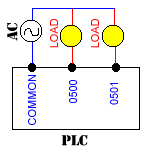
Shown above is a typical method of connecting our outputs to the plc relays. Although our diagram shows the output connected to an AC supply, DC can be used as well. A relay is non-polarized and typically it can switch either AC or DC. Here the common is connected to one end of our power supply and the other end of the supply is connected to the load. The other half of our load gets connected to the actual plc output you have designated within your ladder program.

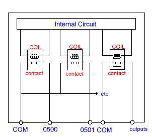
The relay is internal to the plc. Its circuit diagram typically looks like that shown above. When our ladder diagram tells the output to turn on, the plc will internally apply a voltage to the relay coil. This voltage will allow the proper contact to close. When the contact closes, an external current is allowed to flow through our external circuit. When the ladder diagram tells the plc to turn off the output, it will simply remove the voltage from the internal circuit thereby enabling the output contact to release. Our load will than have an open circuit and will therefore be off


0 التعليقات:
إرسال تعليق